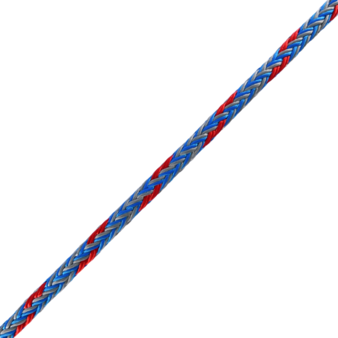
OMEX-RQ - 12-Strand Hollow Braid Performance Rope
OMEX-RQ is a high-performance 12-strand Hollow Braid rope (aka Single Braid), designed specifically for the production of RIGIQ rope-based products.
Constructed from high-tenacity polyester, OMEX-RQ delivers excellent strength, durability, and handling characteristics. Its torque-balanced 12-strand construction provides a firm profile that is easy to inspect, easy to splice, and well suited to the manufacture of arborist rope slings and general rigging products.
OMEX-RQ is made from fully dyed yarns, helping the rope retain its colour throughout use. It is then over-coated with a specialist PU-derived protective coating, engineered to increase abrasion resistance, reduce snagging, enhance wear life, and improve splicing efficiency.
Available in six diameters 10mm, 12mm, 14mm, 16mm, 18mm, and 24mm OMEX-RQ allows a wide range of products to be manufactured to suit different rigging requirements and load applications.
The rope is pre-stretched and heat set to minimise constructional stretch and improve dimensional stability. With its combination of high strength, low elongation, excellent flex fatigue, good UV resistance, and clean splicing performance, OMEX-RQ provides a reliable foundation for the manufactured of arborist rigging products.
Key Features
- Flexible and easy to handle
- High strength per diameter
- Excellent strength-to-weight ratio
- Excellent abrasion and snag resistance
- Good chemical, heat, and UV resistance
- Torque-balanced construction
- Pre-stretched and heat set
- Made from fully dyed yarns to help retain rope colour
- Specialist PU-derived protective coating for extended service life
- Available in 10mm, 12mm, 14mm, 16mm, 18mm, and 24mm
- Designed for manufacturing arborist rope slings
| Product |
Dia |
Weight |
Colour |
MBS - Rope Body |
|
(mm) |
(g/1m) |
|
(kgf) |
(daN) |
| OMEX-RQ 10 |
10 |
71 |
Blue/Grey with Red Tracer |
3302 |
3238 |
| OMEX-RQ 14 |
14 |
119 |
Blue/Grey with Orange Tracer |
3886 |
3811 |
| OMEX-RQ 14 |
14 |
162 |
Blue/Grey with Pink Tracer |
5863 |
5749 |
| OMEX-RQ 16 |
16 |
208 |
Blue/Grey with Yellow Tracer |
7285 |
7145 |
| OMEX-RQ 18 |
18 |
299 |
Blue/Grey with Green Tracer |
9791 |
9601 |
| OMEX-RQ 24 |
24 |
491 |
Blue/Grey with Purple Tracer |
19533 |
19155 |
Rope body: un-terminated:
- Minimum Breaking Strength (MBS) un-terminated.
Important: All product information, specifications and performance data are provided for guidance only and were correct at the time of publication. Specifications may be updated without notice as part of ongoing product development.
Breaking Strength and Maximum Working Load
This product is supplied with breaking strength information (MBS/MBL). A maximum intended working load must be determined by the competent person by applying an appropriate Safety Factor (SF) to the breaking strength and ensuring the expected loads remain below that limit and below the ratings of all other components in the system.
Safety Factors (SF) / Design Factors
System Working Loads Rope and cordage systems are commonly managed using a Safety Factor (SF) (also referred to as a Design Factor or Coefficient of Utilisation). The Safety Factor is the relationship between the products breaking strength (e.g., MBS/MBL) and the maximum intended working load applied during use. The correct Safety Factor depends on the application, the environment, the expected loading type (static or dynamic), and the consequences of failure. In many rope rigging and lowering operations (including tree work), loads may be applied dynamically (e.g., during catches). The system and technique must be planned to minimise peak forces and avoid uncontrolled shock loading such as excessive free-fall, abrupt stops, or hard catches.
Typical Safety Factor guidance (set by the competent person/system designer):
- 5:1 commonly used in controlled lifting system design
- 7:1 commonly used for textile lifting slings in many EN-rated systems
- 10:1 (or higher) often applied in rope rigging and lowering where dynamic effects and higher peak loads may occur
Important: These figures are provided as general guidance only. The required Safety Factor may be higher depending on the risk assessment, local regulations, industry practice, and operational conditions.
Note on terminology: WLL is typically a single limit assigned to equipment by the manufacturer under a defined standard. For rope systems, the competent person may determine a system working load / maximum intended working load by applying a Safety Factor appropriate to the task and conditions.
Always inspect rope and equipment before and after use. Retire any product showing signs of damage, excessive wear, contamination, heat damage, chemical exposure or other deterioration. Use only by trained and competent persons and in accordance with relevant industry best practice.